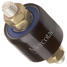
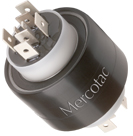
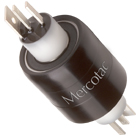
Model 305
| Model 305 Three Conductors, 4 Amps
|
 |
|
Stainless steel ball bearing standard |
||

| Model No. | Terminals | Voltage AC/DC |
Amp Rating @240VAC |
Max. Freq. MHz |
Contact Resistance |
Max. RPM |
Temp Max. F (C) / Min. F (C) |
Rotation Torque (gm-cm) |
Circuit Separation |
| 305 | 3 | 0-250 | 4 | 200 |
|
1800 | 140 (60) /45(7) | 100 |
|
||||
| 305-L | 3 | 0-250 | 4 | 200 |
|
1000 | 140 (60) /-20(-29) | 100 |
|
 |
|
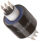
| 593 three contact receptacle w/ 6" wires (18 AWG) |
553 three contact cap w/solder lugs |
|
Receptacle used for mounting to rotating device.
|
|

|
|
|
| Note: The outer shell of the metal receptacle used for mounting is electrically conductive. | |


|
||||
|
Receptacle Mount Hole Dimensions |
||||
| MODEL | HOLE DIAMETER (Ø) * | DEPTH | ||
| 593 | .408" (10.36) | .35" (8.89) | ||
| *Inch (mm) Tolerance Ø | +.001" (+.025) | |||
| -.000" (-.000) | ||||
|


Installation Notes:
|
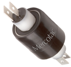
Model 330
| Model 330 Three Conductors, 30 amps
|
 |
|
Disconnects included (6 lg.) Boot kit available Available with stainless steel ball bearing (330-SS) |
||

| Model No. | Terminals | Voltage AC/DC |
Amp Rating @240VAC |
Max. Freq. MHz |
Contact Resistance |
Max. RPM |
Temp Max. F (C) / Min. F (C) |
Rotation Torque (gm-cm) |
Circuit Separation |
| 330 | 3 | 0-250 | 30 | 100 |
|
1200 | 140 (60) /-20(-29) | 300 |
|
||||
| 330-SS | 3 | 0-250 | 30 | 100 |
|
1200 | 140 (60) /-20(-29) | 300 |
|
 |
 |
| 55251 Terminal 16 - 14 AWG (qty. 3 included) |
57430 Boot Kit for dust or splash protection IP51 |
| 55253 Shrink Tube (qty. 3 included) |
55252 Terminal 16 - 14 AWG (qty. 3 included) |
|
Terminals for other wire gauges available. |
|
|
|
|

|
||||||||||||||||||||||||||||||||
|
||||||||||||||||||||||||||||||||
|
||||||||||||||||||||||||||||||||

 |
 |
 |
 |
 |
 |
 |
 |
 |
 |
Installation Notes:
|
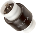
Model 331
| Model 331 Three Conductors, 2@4amps, 1@30amps
|
 |
|
Disconnects included (4 sm., 2 lg.) Boot kit available Available with stainless steel ball bearing (331-SS) |
||

| Model No. | Terminals | Voltage AC/DC |
Amp Rating @240VAC |
Max. Freq. MHz |
Contact Resistance |
Max. RPM |
Temp Max. F (C) / Min. F (C) |
Rotation Torque (gm-cm) |
Circuit Separation |
| 331 | 3 | 0-250 | 2@4/1@30 | 100 |
|
1800 | 140 (60) /-20(-29) | 200 |
|
||||
| 331-SS | 3 | 0-250 | 2@4/1@30 | 100 |
|
1800 | 140 (60) /-20(-29) | 200 |
|
|
 |
| 55251 Terminal 16 - 14 AWG (qty. 1 included) |
57230 Boot Kit for dust / splash protection IP51 |
| 55250 16 - 14 AWG (qty. 1 included) |
55110 22 - 18 AWG (qty. 4 included) |
|
Terminals for other wire gauges available. |
|
|
|
|

|
||||||||||||||||||||||||||||||||
|
||||||||||||||||||||||||||||||||
|
||||||||||||||||||||||||||||||||

|
|
|
|
|
|
|
|
|
|
Installation Notes:
|
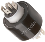
Model 335
| Model 335 Three Conductors, 3@30amps & 500V
|
 |
|
Disconnects included (6 lg.) Boot Kit available Available with stainless steel ball bearing (335-SS) |
||

| Model No. | Terminals | Voltage AC/DC |
Amp Rating @240VAC |
Max. Freq. MHz |
Contact Resistance |
Max. RPM |
Temp Max. F (C) / Min. F (C) |
Rotation Torque (gm-cm) |
Circuit Separation |
| 335 | 3 | 0-500 | 30 | 100 |
|
500 | 140 (60) /-20(-29) | 700 |
|
||||
| 335-SS | 3 | 0-500 | 30 | 100 |
|
500 | 140 (60) /-20(-29) | 700 |
|
 |
|
|
| 57335 Boot Kit for dust or splash protection IP51 |
55250 Terminal 16 - 14 AWG (qty. 3 included) |
55251 Terminal 16 - 14 AWG (qty. 3 included) |
| Terminals for other wire gauges available. (22-18 AWG and 12-10 AWG) |
||
|
|

|
||||||||||||||||||||||||||||||||
|
||||||||||||||||||||||||||||||||
|
||||||||||||||||||||||||||||||||

|
|
|
|
|
|
|
|
|
|
Installation Notes:
|
MERCOTAC MARKASINA A?T ?R?N GRUPLARI